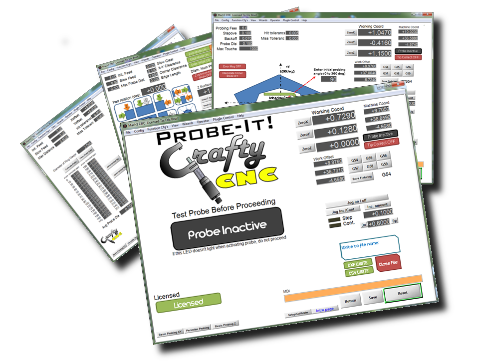
Thanks for your interest in Probe-It!, a wizard add-on for the popular Mach3 CNC control software. I began writing Probe-It! to be able to provide functionality in Mach3 I didn’t see provided by any other options, even after much searching in forums and on the web…
Probe-It! provides some of the same general functionality as found in other existing probing macros and wizards such as:
- General/simple measurements
- Locating positions of corners, edges, and centers of bores
- Setting origins on pieces to be machined easily (edge finder functionality)
Probe-It! also provides some features useful for measuring and reverse engineering, such as:
- Ability to ‘calibrate’ the probe tip (calibration accounts for errors in probe tip deflection, and backlash within reason) – Now with 2 optional modes!
- Mode 1: If your probe is mechanically runout free (ball tip is concentric with shank/spindle), calibration option 1 auto-finds the center of the gauge ring and runs twice to calibrate deflection errors in the probe
- Mode 2: If your probe has runout, or is non-adjustable, you can manually locate the spindle to the center of the ring gauge (use DTI, co-ax indicator, etc) before calibrating with option 2. Option 2 builds a full correction table that then accounts for the ‘offset’ in the probe tip to the shank/spindle center line. This method is more sensitive to you re-installing the probe in same orientation in spindle every time.
- Ability to probe in any sort of vector in the X-Y plane, with result corrected by calibration data
- Automatic 2.5D perimeter tracing (not a bed of nails approach in 3D space, which doesn’t provide an accurate ‘outline’ of 2D parts)
- Ability to record data direct to a DXF or CSV file for later analysis or usage in a CAD program
- Logic added to probing routines to detect a ‘hit’ or a ‘miss’
- Ability to probe parts/features not square to the table (part rotation)
- Auto Z up/down as part of basic x-y probing routines
- NEW in V1.1.3: Auto rotated coordinates (G68) routine
- NEW in V1.1.3: Single line surface profile trace in X/Z plane routine.
The goal of Probe-It is to provide a useful tool with functionality I couldn’t find anywhere else. Probe-It! doesn’t include other probing features already existing or available, for example the 3D ‘bed of nails’ approach which is in a Wizard shipped with Mach3, is not found in Probe-It!. Please review the HELP page to download a copy of the manual in PDF format, and to see some of the basic requirements to run Probe-It.
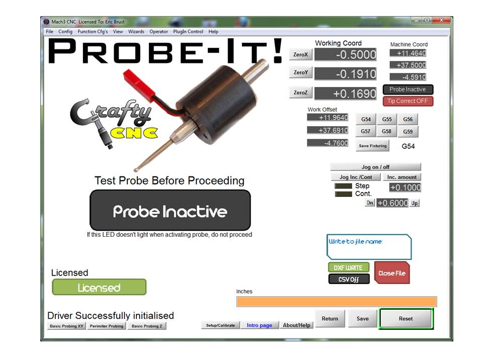
The Intro Page
The introduction page is the default page that Probe-It opens to. It serves one simple yet important purpose… Test your probe out and verify the big LED on the Mach3 screen lights up when you activate the tip before you do any probing! This verifies your probe hardware, wiring, and Mach3 port/pin setup!
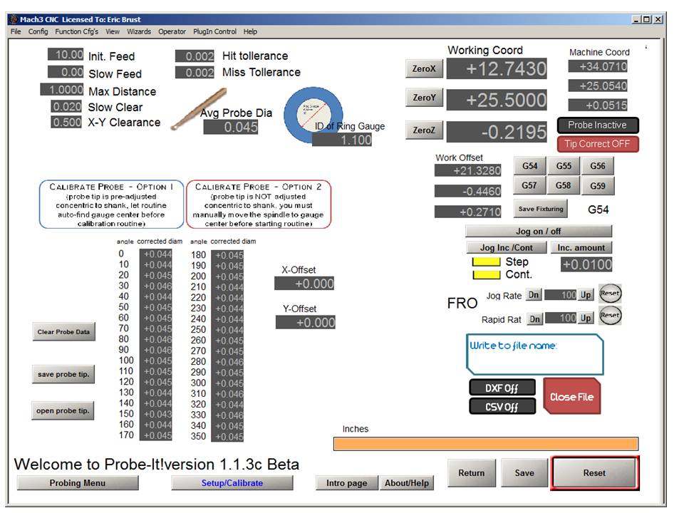
The Setup and Calibration page
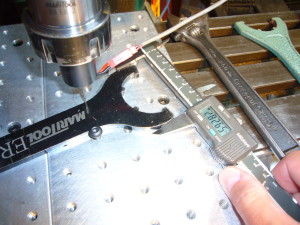
The Calibration and Setup page is where you set some of the basic parameters, and have the option of creating a probe tip calibration table. When you create a calibration table, you probe the ID of an accurate and round ‘gauge ring’ that you provide the actual measured inner diameter. The probe routine builds a table of ‘compensated tip diameters’ for every 10 degree angle directions. The compensation can correct for probe trip deflections, backlash, etc and results in the ability to probe parts and perimeters very accurately. You can select from two methods of calibration depending on your probe. If your probe tip is mechanically centered to the shank (Prefered!), then run option 1 to create a table that compensates for tip deflections and backlash. If your probe tip has mechanical runout, use option 2 to create a calibration table that includes an X/Y offset for the tip to shank error. This method is less ideal, as you must re-install the probe at the same angle everytime. In addition, you must be able to center your spindle to the gauge ring BEFORE running the option 2 calibration routine to get the correct offsets measured.
XY Probing Routines Page
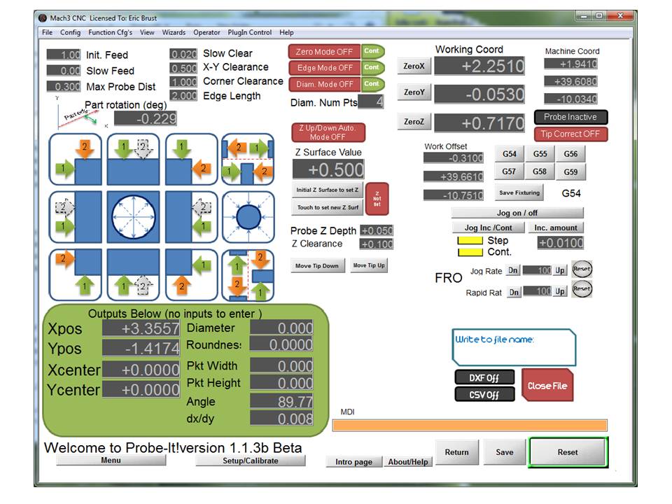
The XY Probing page provides several canned routines that probe sides, corners, edges, ID bores, slots, etc. All of the routines provide dimensional measurement info (CMM like usage) and the option to zero the axis to probed features (setup). Data may be saved to a CSV file (CMM like measurement recording) or to a DXF to build up CAD file of probed geometry.
There is also the option to have the Z auto raise/lower, which will allow jogging from location to location and running probing routines without having to constantly raise and lower the probe tip. You can also ‘rotate’ all the probing routines by an angle entered in the ‘part rotation’ DRO.
Perimeter Probing Routines Page
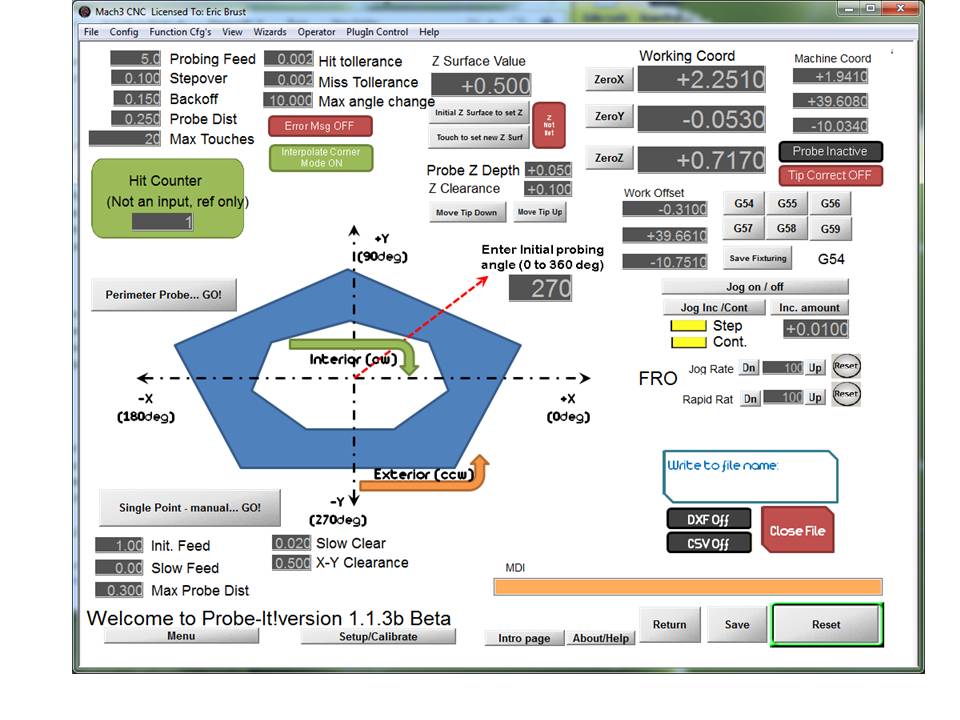
The Perimeter probing routine is really what Probe-It! was written to do. Up till now I’ve not found an easy way to get accurate 2-D profiles recorded into something usefull for reproducing a 2-D or 2.5D type of object, which is mostly what is required for reverse engineering of simple parts! The 3D ‘bed of nails’ routines in the bundled Mach3 Wizards are great for probing away at a coin or a toy car and giving you a point cloud, but if you accurately want to reproduce a profile shape, say a guitar body, or hole patterns in a plate, etc the ‘bed of nails’ route won’t really get you there.
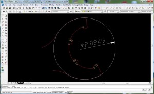
The perimeter probing routine in Probe-It needs just a few inputs from the user to indicate where you are starting on the part, how far to step over between probe locations (how coarse to probe the exterior), and how far to move back for clearance and it will trace around the perimeter. Points recorded are either saved to a CSV or a DXF file (or both at once). The probing routine attempts to always probe ‘squarely’ against the perimeter of the object and used the tip correction look-up table to be as accurate as possible. When the routine runs into an abrupt change, it will attempt to interpolate the corner as a 90 degree direction change and record a point at the assumed intersection. This may not be fully accurate, but it is easy enough to edit the DXF files to fix the geometry, and the interpolated ‘guess’ points are indicated by circles to highlight them.
X/Z Surface Page (New in V1.1.3)
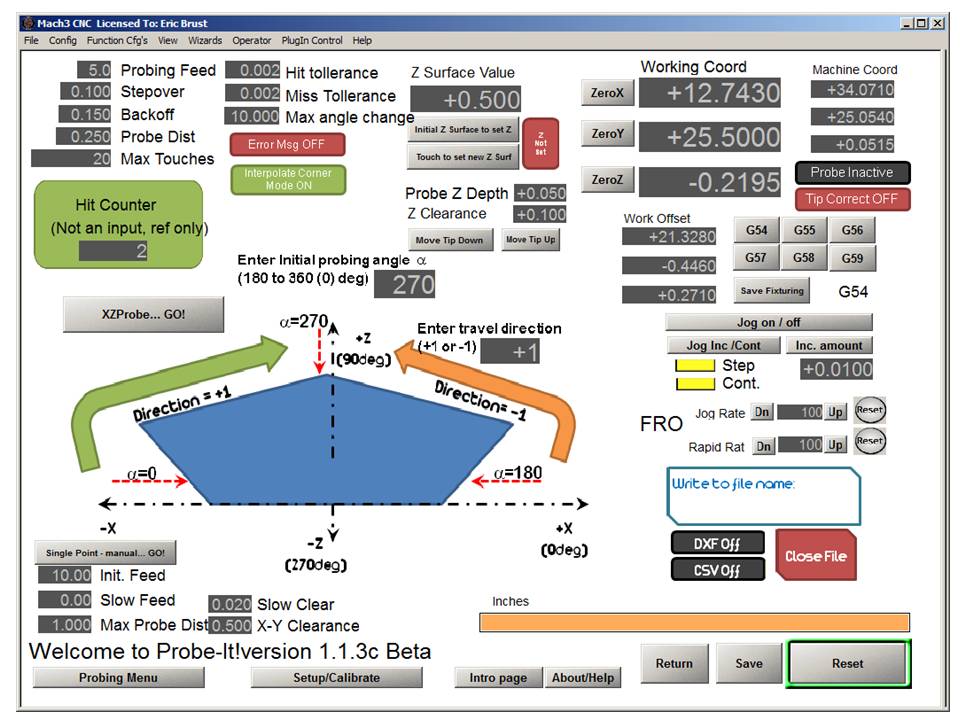
This routine is ‘preliminary’ but functional. This takes the X/Y perimeter tracing routine, and turns it into a surface tracing routine that works in the X/Z plane. The inputs and function are nearly identical to the X/Y perimeter routine, with the addition of a ‘travel direction’ input, which tells the routine to work in the +X direction or the -X direction.
Auto G68 Routine (New in V1.1.4)
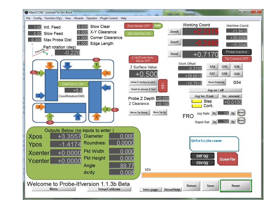
This routine is meant to be an additional method of setup for machining operations. If your part is not ‘square’ to the axes/table, you can probe along an edge / corner combination to automatically set coordinate system rotation (G68), and define a corner as X/Y zero.
Simple Z Probing Page
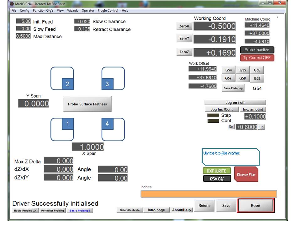
The simple z probing page does one simple thing at the present time, it will probe along two points along either the X or Y axis, or it will probe 4 points in a square X/Y pattern and display the maximum Z delta. This is usefull for setting up and ‘shimming’ your plate stock if you are working off the table or using material which isn’t necessarily flat.
You simply enter in the X or Y (or both X and Y) spacing, start in the lower left hand corner of your workpiece, and let the routine run.
The Current Version of ProbeIt is V1.1.5
REQUIREMENTS:
* You must have Mach3, version 3.43.19 or later. I recommend the latest lock down or 3.43.66 or later.
* You need to have a probe setup that triggers the ‘digitize’ input in Mach3. You may test by assigning a keyboard key to be a ‘probe’ input if you don’t have a probe, but it still requires that you have the parallel port driver installed and an assigned key setup in ‘ports and pins’.
* This wizard IS NOT COMPATIBLE with MachStdMill from Calypso Ventures, and cannnot be run while using MachStdMill Screenset due to conflicting use of DROs/LEDs/etc. A workaround to use this wizard is to setup another Mach3 Profile that uses a standard screenset.
* This wizard is tested to work on machines driven from the standard parallel port, a Smoothstepper, CNC Drive UCx00, or CSMIO. There is NO guarantee that it will work properly with any other external motion control device, as probing is handled within the motion controllers and not Mach. Test at your own risk.
**WARNING** If you have a generic Chinese made external motion device, such as a ‘Digital Dream’ or similar, do not bother trying this wizard. Probing is not implemented correctly in these devices, and they have been reported to produce random moves which may damage your probe. This has been reported by a few users now.
